[ad_1]
howdy,
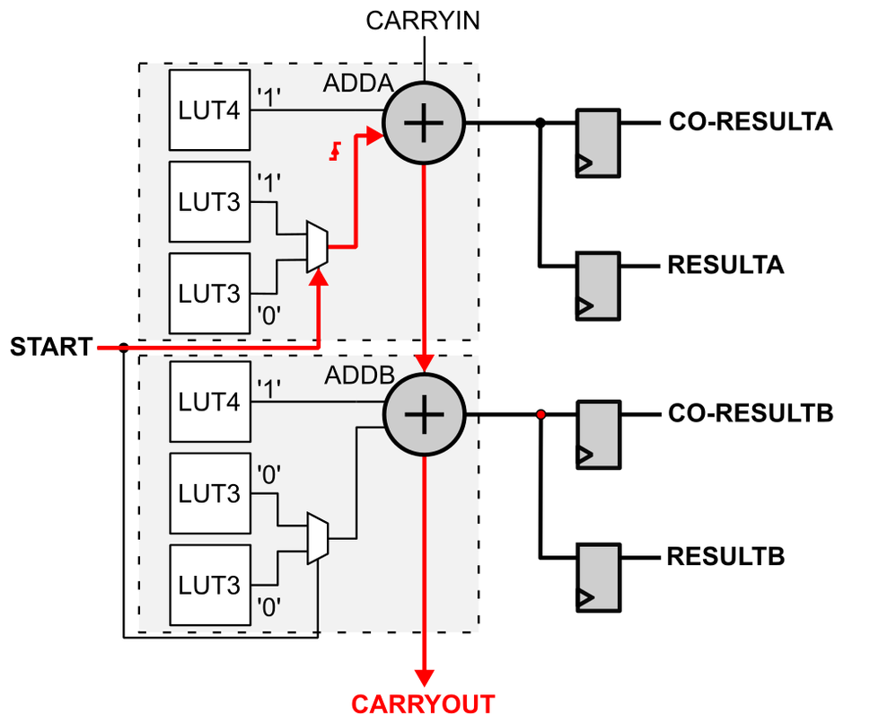
I’m attempting to implement a time-to-digital converter in Arria 10 FPGA, the schematic of which I’ve proven within the connected determine. I’ve many issues with this circuit due to its optimization by Quartus software program.
To begin with, in HDL I described an adder to carry out “0…0″&begin + “1…1” operation. To cease the optimization I needed to describe the worth “1…1” as a sign with the preserve attribute. This makes this sign in a roundabout way connected to Vcc however is produced by further ALM blocks, so it will increase the consumption of logic sources. Is it doable to repair this? Observe that I’ve already attempt to use CARRY_SUM primitive, adder IPs and behavioral description, all with the identical outcomes.
Subsequent, a good greater drawback is to attach the output of the adder concurrently to 2 corresponding flip-flops. Based on documentation, it needs to be doable in ALM arithmetic mode. Nonetheless, throughout compilaion further “feeders” (buffers carried out in look-up tables) are added which trigger implementations of the second flip-flop in one other ALM block. Within the article [Cyclone10_TDC], the authors acknowledged that they achieved this configuration by utilizing two clock inputs to the ALM (e.g. clk(0) for the primary flip-flop and clk(1) for the second), however in my case it did not work. I additionally tried varied synthesis attributes, however with out success.
In a ChipPlanner I used to be capable of manually set ALM for the specified configuration however how can I save this configuration and use in HDL?
[ad_2]